ENGINEERING SELECTION GUIDE · OCTOBER 27, 2026
Thin Section Bearing Selection: Type A, C and X
Compare angular, radial and four-point contact thin section bearings, same-envelope alternatives, sealing and the information needed for an interchange review.
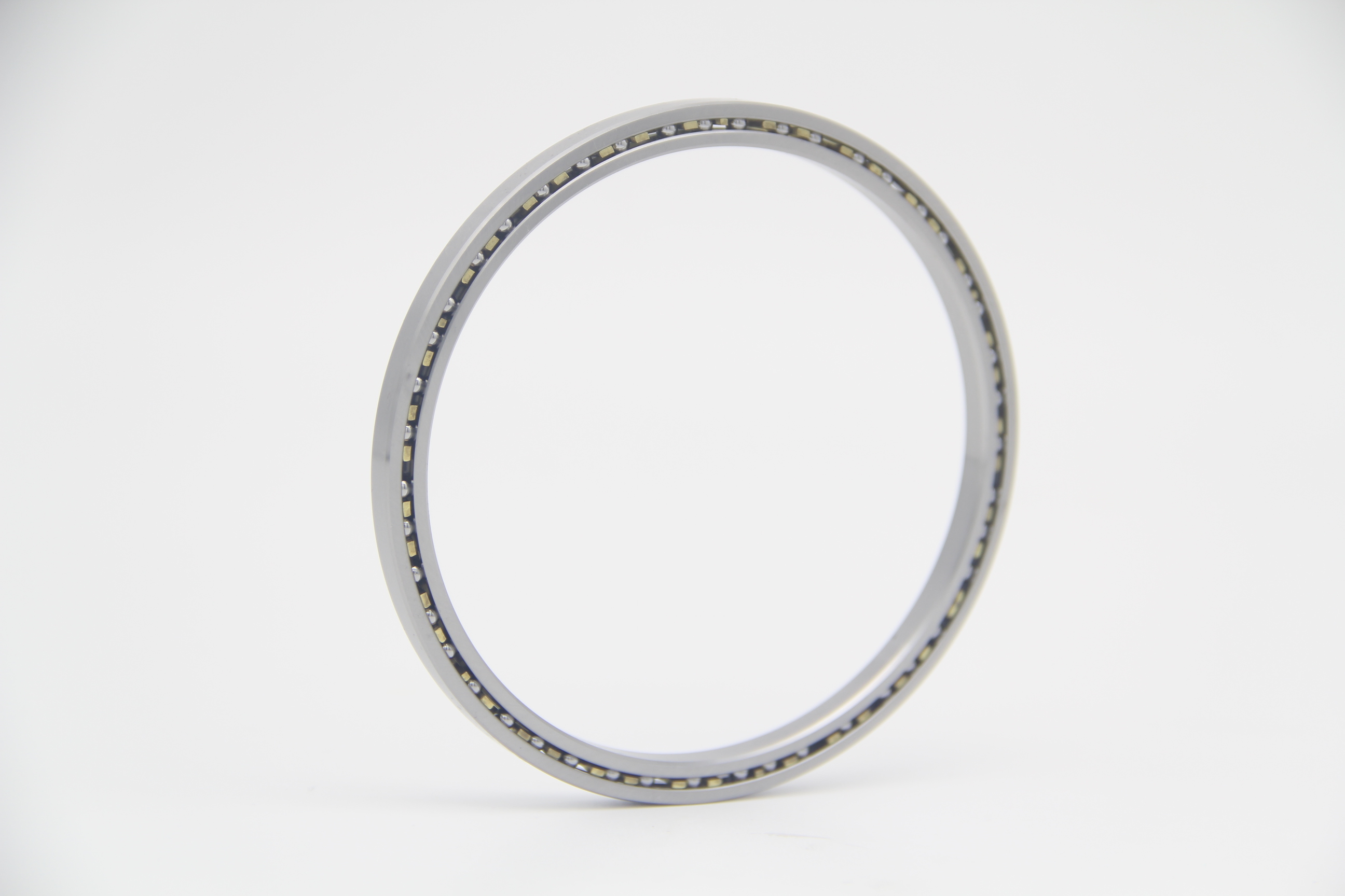
Start with the load arrangement
A bore and outside diameter establish part of the mounting envelope. They do not identify the contact geometry, clearance or arrangement that carries the load. Record the radial load, axial load in each direction, overturning moment, speed and operating cycle before reviewing an alternative.
Thin section reference families can share nominal dimensions while using different contact designs. A catalogue comparison should show those differences explicitly so the application can be reviewed.
Compare Type A, C and X
| Type | Arrangement to review | Information needed |
|---|---|---|
| A: angular contact | Axial load direction and the opposing bearing arrangement | Pairing, mounting orientation, clearance or preload, temperature |
| C: radial contact | Radial shaft support and any required axial location | Radial load, support spacing, axial and moment loads for review |
| X: four-point contact | Combined radial, axial and moment loading | Simultaneous load cases, mounting stiffness, speed and duty cycle |
For example, KA020CP0, KA020AR0 and KA020XP0 share a 2.000 in bore and 2.500 in outside diameter. Their contact designs and catalogue ratings differ. Review the change in load arrangement before substituting one for another.
Keep bore, section and shoulder support separate
A matching bore does not establish a matching outside diameter. KF040AR0 has a 4.000 in bore, 5.500 in outside diameter and 0.750 in section. Compare all envelope dimensions and the land or counterbore dimensions with the mating shaft and housing drawings.
Show the bearing seats, axial locating faces and tolerances. The schematic envelope drawing on a model page supports preliminary comparison; it does not define internal raceway geometry or replace a manufacturing drawing.
Worked comparison: one bore, three different envelopes
These three open angular-contact references all have a 4.750 in bore. Moving between the KA, KD and KF sections changes the outside diameter, shoulder geometry and catalogue ratings. Compare the installation space before reviewing a possible change in capacity.
Review seals, lubricant and starting torque
Open and sealed references may have the same principal dimensions. For example, J05008CP0 and K05008CP0 both use a 50 mm bore and 66 mm outside diameter, with different sealing configurations.
Provide contamination and moisture exposure, operating temperature, lubrication method and acceptable starting torque. Confirm seal material and lubricant compatibility for the actual environment.
Worked comparison: the same outside diameter can hide a different bore
JA045XP0 and JU042XP0 are both sealed Type X references with a 5.000 in outside diameter. JA045XP0 has a 4.500 in bore and 0.250 in section; JU042XP0 has a 4.250 in bore and 0.375 in section. A housing-diameter match therefore does not establish a shaft or shoulder match.
For metric combined-load layouts, J02508XP0 provides an 8 mm section around a 25 mm bore. The open radial-contact K11008CP0 uses the same nominal section around a 110 mm bore. Section size, contact design and bore identify different selection requirements.
Use catalogue ratings as reference data
Dynamic and static ratings describe different selection conditions. Keep their units explicit, including pounds and newtons, and send the complete combined-load case. A missing thrust or moment rating does not mean that an unreviewed load can be applied.
Final PRIUS capacity, clearance, material and life requirements are confirmed through an application and drawing review. Reference-brand catalogue values are not a guarantee of an independently supplied product's performance.
Prepare a useful interchange enquiry
- Complete model and suffix, required quantity and the original drawing or catalogue page.
- Shaft and housing drawing, fits, land support, material and tolerance requirements.
- Loads, load directions, speed, duty cycle, operating temperature and environment.
- Contact arrangement, clearance or preload, seal and lubricant requirements.
Kaydon and Reali-Slim names identify the original catalogue references. PRIUS BEARINGS is an independent alternative supplier. Compatibility is established by the confirmed drawing and application requirements.
Technical references
Kaydon Reali-Slim engineering and selection catalogue
Use the current original drawing and your application conditions when evaluating a specific reference.
Send your model and application
Email drawings or photos to sales@priusbearing.com, or use the quotation form with the model and required quantity.
Request an engineering review →